
TERMS OF LINEAR GUIDE
1-1 Major Factors
a. Load and Life (L)
Choosing a linear guide has to consider the following variables to conclude a reliable static safety factor: average applied load on every slide, basic static nominal load(C0) or basic permissible static moment(Mx、My、Mz). In case of calculating life in a long-term consumed environment, it requires basic dynamic nominal load(C) for an approximate result.b. Basic static load rating (C0)
When a linear motion system in the static state or in motion is subject to an extreme load or impact, a permanent deformation will occur between raceway and rolling elements. If the deformation is excessive, the linear motion system can not travel smoothly. Now, we define the basic static nominal load(C0) is a static load of constant magnitude acting in one direction under which the sum of the permanent deformations of rolling elements and raceway equals 0.0001 times the diameter of the rolling elements.c. Basic permissible static moment
When a linear guide gets a force that makes the balls distorted to 1/10,000 of theirs diameter, we call the force as basic permissible static moment.d. Static safety factor (fs)
The static safety factor indicates the ratio of Basic static nominal load(C0) to the load acting on the linear motion system.e. Nominal life (L)
The nominal life L is the total distance of travel reached without flaking by 90% of a group of identical linear motion system that are operated independently under the same condition.f. Basic dynamic load rating(C)
When each of a group of identical linear motion system is applied independently under the same condition, basic dynamic load rating C is the load of constant magnitude acting in one direction that results in a nominal life of 50 km for a system using balls.1-2 Subsidiary Factors:
a. Contact factor (fc)
In linear motion system, it is hard to obtain uniform load distribution in close contact installation due to moments, errors on the mounting surfaces and other factors. When two or more blocks in a rail are used in close contact, multiply basic load ratings C and C0 by the contact factors shown below.
|
Number of blocks in close contact |
Contact factor |
|
2 |
0.81 |
|
3 |
0.72 |
|
4 |
0.66 |
|
5 |
0.61 |
|
Normal operation |
1 |
b. Hardness factor (fh)
When working environment temperature exceeds 100 degrees Celsius, ft becomes a key factor.
c. Temperature factor (ft)
When working environment temperature exceeds 100°C, ft becomes a key factor.

Remark:
When working environment temperature exceeds 80 degrees Celsius, the material of seals and cages have to be able to endure the high temperature.
d. Load factor (ft)
Reciprocating motion usually occur vibrations, impacts and variable loads. In general, vibrations occur in high-speed operation, impacts due to repeated starting and stopping and variable loads; therefore, it is difficult to calculate.
1-4 Friction resistance
Friction can be calculated by:
F = u * W + f
F : Friction resistance
W : Load
u : Coefficient of friction
f : Block seals resistance
II. APPLYING LINEAR GUIDE

1. Confirming conditions
It takes engineering calculation when adapting a linear guide system, and the must knows are:
A. Composition: (distance between 2 blocks / rails number of blocks, number of Rails.)
B. Mounting: (Horizontal, erect, on a slant, wall installation, or upside down Mounting.)
C. Applied load
D. Frequency of use
A. Composition:
1. Distance between 2 blocks / rails: L0&L1 as shown.
L0: Distance of two blocks loaded on the same rail (mm)
L1: Distance between one rail to another (mm)
The distance of L0 and L1 matters the rigidity and life of the linear guide system itself.
2. Number of blocks: in general cases, the more blocks used on a rail, the better the rigidity and the higher load capacity. However, layout plan and stroke have to be reconsidered.3. Number of rails: when increasing the quantity of rail, the moment resistance of X axis enhances and so do rigidity and load.
b. Installation:
1.Horizontal Installation
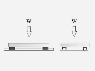
Horizontal Installation(W:load in direction of compression)
The commonest position of setting a linear guide.
Application: positioning or feeding.
W is vertical to the table mounting on the blocks.W is vertical to direction of system movement.
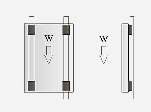
Erect Installation(W:load in direction of compression)
Application: elevating device.
W is parallel to working table.W is parallel to direction of system moving.
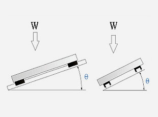
Slanting Installation(W:load in direction of compression)
Side slanting: W is vertical to direction of system moving.
Front slanting: Angleθ between W and direction of movement。
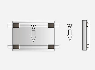
Wall Installation(W:load in direction of compression)
Distance between 2 rails ahs to be considered.
W is parallel to working table.W is vertical to direction of system moving.
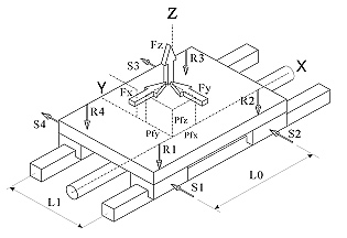
c. Applied load
Load contains 3 elements: force, direction of load and object that is loaded.Force: Weight: it produces inertia when it moves.
Direction of load: Can be divided into 3 dimensions.
Shown as Fx, Fy and Fz on fig.
Position of load acts: Pfx, Pfy and Pfz are shown as fig, defined as distance from applied load to center of driving power.
Driving power could be actuated by a ball screw, an oil pneumatic cylinder or a linear motor.
Distance between 2 carriages / rails: L0 & L1: as shown
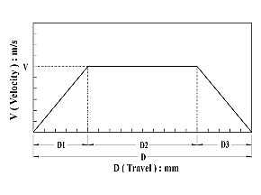
V/D figure:
Velocity (V): The highest speedDistance (D): Distance that the system runs.Multi Colors Injection Molding
(D1): Distance moving from static to the highest speed
(D2): Distance at equivalent speed
(D3): Distance moving from the highest speed to static Forces onto Carriages:
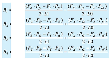
R1、R2、R3、R4 are forces from vertical directions
S1、S2、S3、S4 are forces from horizontal directions
d. Frequency of use:
Frequency of use has to be added into considerations when proving whether the engineering calculation fit the actual application.
2-3 Selecting An Optimal Model
BGX or BGC
Choosing workable size should be based on the type of the machine center.
Introductions of BGC and BGX of linear guide are attached in the following
content.
b.15、20、25、30、35
Size should be the first point as selecting a linear guide for a new working system because load and exact life are difficult to calculate at the beginning. As the result, when there is a difference between calculated life and actual load, move to a size with larger dynamic load rating.
2-4 Calculating Applied Load:
Equation of vertical forces onto the block.
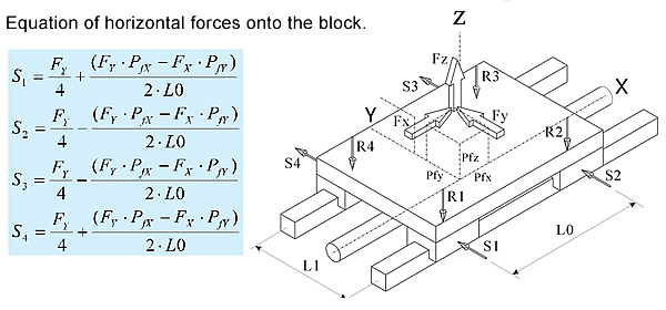
2-5 Calculation Of Equivalent Load
The contact arc between a rail and a block decides the ratio of those forces from horizontal and vertical directions which happening to the block. Equivalent load means the maximum force that the groove could take. It needs to have the vertical and horizontal forces to calculate the equivalent load, and distribute it by different directions. For instance, the load of 45° design is the absolute value of horizontal force plus the absolute value of vertical force.
Rn: Divided vertically load
Sn: Divided horizontally load
Equivalent load Re comes from:
Re = │Rn│+│Sn│
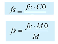
2-6 Confirming Static Safety Factor
Definition of safety factor
Calculating fs with static load rating:
Calculating fs with permissible static moment:
Contact factor (fc)
In linear motion system, it is hard to obtain uniform load distribution in close contact installation due to moments, errors on the mounting surfaces and other factors. When two or more blocks in a rail are used in close contact, multiply basic load ratings C and C0 by the contact factors shown below.
| Number of blocks in close contact | Contact factor |
| 2 | 0.81 |
| 3 | 0.72 |
| 4 | 0.66 |
| 5 | 0.61 |
| Normal operation | 1 |
2-7 Reference Of Static Safety Factor
Reference value of static safety factor fs shown below:
|
Operating condition |
Load condition |
Minimum fs |
|
Normally stationary |
Small impact and deflection |
1.0 ~ 1.3 |
|
Impact or twisting load are applied |
2.0 ~ 3.0 |
|
|
Normally moving |
Small impact or twisting load are applied |
1.0 ~ 1.5 |
|
Impact or twisting load are applied |
2.5 ~ 5.0 |
2-8 Calculating Mean Load
Calculation of changing mean load can be diversified into the following models:
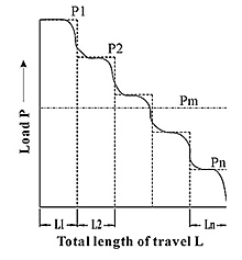
STEP LOAD:

Pm = [(P1nxL1+P2nxL2….. +PnnxLn)/L] 1/n
Pm: Mean load (kgf)
Pn: Varying load (kgf)
L: Total length of travel (mm)
Ln: Length of travel carrying Pn (mm)
n=3 when the rolling elements are balls.
線性負載型式
Pm≒(Pmin+2xPmax)/3Pmim: Minimum load (kgf)
Pmax: Maximum load (kgf)

2-9 Calculating Nominal Life

L: Nominal Life (km)
C: Basic dynamic rating load (kgf)
P: Calculated average load (kgf)
fc: Contact factor
fh: Hardness factor
ft: Temperature factor
fw: Load factor
2-10 Calculating Life Time
Formula A: calculating hour Ln: Lifetime (h)
L: Nominal life (km)
Ls: Distance of travel (mm)
N1: Times of travel per minute (min-1)
Formula B: calculating year
Ly: Lifetime (year)
L: Nominal life (km)
Ls: Distance of travel (mm)
N1: Times of travel per minute (min-1)
M: Minutes of running per hour (min/hr)
H: Hours of running per day (hr/day)
D: Days of running per year (day/year)

2-11. Comparing With Desired Life
If comparing the calculated life and desired life and come up with an unacceptable difference, look back to the flow chart:1. Confirming conditions
2. Selecting an optimal mod
1. Reconfirming the conditions of use:
a. Composition?
i. Distance of each two rails and blocks
ii. Number of blocks
iii. Number of rails
b. Mounting: how the rail is mounted onto the system?
c. Load capacity?
d. Frequency of use?
2. Selecting another model:
When conditions of use cannot be changed, select another feasible model is suggested. In addition, choosing another block of the same size with heavier load capacity is firstly recommended. Replacing the original choice with other sizes, such as size 15 to size 20, would raise the cost and add changes to the design. Contact us when technical assistance is required.
2-12 Model Number Coding

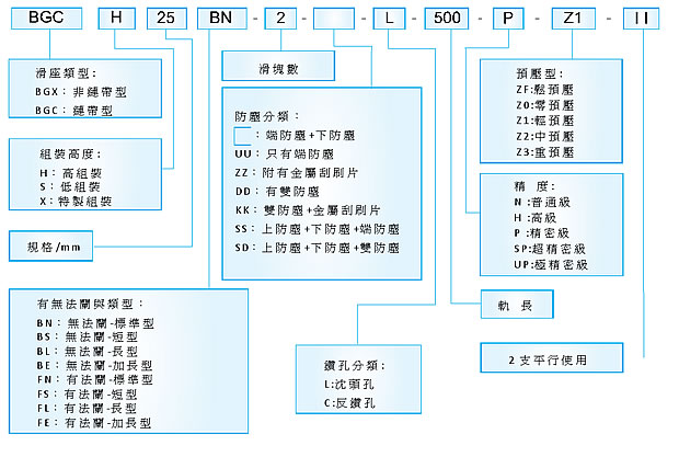

Unit: mm
|
ITEM GRADE |
Normal(N) |
High(H) |
Precision(P) |
Super-Precision(SP) |
Ultra-Precision(UP) |
|
Tolerance of height ( H ) |
±0.1 |
±0.04 |
0 |
0 |
0 |
|
Tolerance of width ( W ) |
±0.1 |
±0.04 |
0 |
0 |
0 |
|
Difference of heights (△H ) |
0.03 |
0.02 |
0.01 |
0.005 |
0.003 |
|
Difference of widths (△W ) |
0.03 |
0.02 |
0.01 |
0.005 |
0.003 |
|
Running parallelism of BR Block surface |
△C Refer to the below Fig. BG rail length and running parallelism |
||||
|
Running parallelism of BR Block surface |
△D Refer to the below Fig. BG rail length and running parallelism |
||||

b. Choosing preload
Replacing larger rolling elements helps strengthening the entire rigidity of the
carriage while there exists clearance within ball circulation.
|
Preload |
Slight clearance/ |
Light preload (Z1) |
medium/ heavy |
|
Conditions |
1. Light corrosion |
1. Cantilever |
1. Heavy corrosion |
|
Application |
1.Welding machine |
1. NC Lathe |
1. Machine center |
Increasing preload would diminish the vibration and reduce the corrosion caused by running back and forth. However, it would also add the workload within those rolling elements. The greater the preload, the greater the inner workload. As a result, choosing preload has to consider both how vibration and preload would affect life and conclude an optimal choice.
Preload grade
| C:Basic dynamic load rating | ||
| GRADE ITEM |
Symbol |
Preload force |
|
Clearance |
ZF |
0 |
|
No Preload |
Z0 |
0 |
|
Light Preload |
Z1 |
0.02C |
|
Middle Preload |
Z2 |
0.05C |
|
Heavy Preload |
Z3 |
0.07C |
| Unit: μm | |||||
| Symbol Type |
ZF | Z0 | Z1 | Z2 | Z3 |
| BG 15 | 5~12 | -4~4 | -12~-5 | -20~-13 | -28~-21 |
| BG 20 | 6~14 | -5~5 | -14~-6 | -23~-15 | -32~-24 |
| BG 25 | 7~16 | -6~6 | -16~-7 | -26~-17 | -36~-27 |
| BG 30 | 8~18 | -7~7 | -18~-8 | -29~-19 | -40~-30 |
| BG 35 | 9~20 | -8~8 | -20~-9 | -32~-21 | -44~-33 |
| BG 45 | 10~22 | -9~9 | -22~-10 | -35~-23 | -48~-36 |
Interchangeability
|
Accuracy |
Non - interchangeable |
Interchangeabl |
|||||
|
UP |
SP |
P |
H |
N |
H |
N |
|
|
Preload |
|
|
|
|
ZF |
|
ZF |
|
|
|
Z0 |
Z0 |
Z0 |
Z0 |
Z0 |
|
|
Z1 |
Z1 |
Z1 |
Z1 |
Z1 |
Z1 |
Z1 |
|
|
Z2 |
Z2 |
Z2 |
Z2 |
Z2 |
|
|
|
|
Z3 |
Z3 |
Z3 |
|
|
|
|
|

|
ITEM |
Unit: μm | |||||||||
|
e1 |
e2 |
|||||||||
|
Z3 |
Z2 |
Z1 |
Z0 |
ZF |
Z3 |
Z2 |
Z1 |
Z0 |
ZF |
|
|
BG 15 |
|
|
18 |
25 |
35 |
|
|
85 |
130 |
190 |
|
BG 20 |
|
18 |
20 |
25 |
35 |
|
50 |
85 |
130 |
190 |
|
BG 25 |
15 |
20 |
22 |
30 |
42 |
60 |
70 |
85 |
130 |
195 |
|
BG 30 |
20 |
27 |
30 |
40 |
55 |
80 |
90 |
110 |
170 |
250 |
|
BG 35 |
22 |
30 |
35 |
50 |
68 |
100 |
120 |
150 |
210 |
290 |
|
BG 45 |
25 |
35 |
40 |
60 |
85 |
100 |
140 |
170 |
250 |
350 |

Cap:
Most chippings are blocked by end seals, but some would stay in the screwholes. Caps are accessory that can prevent the entry of chippings.
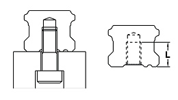
Rail with tapped holes:
Fixing a rail with tapped hole is different from fixing a standard one. A major
strength of it is the shape of the tapped hole (shown as fig.); dust and chippings
would not enter.
|
Size |
Screw |
Length of thread |
|
BG 15 |
M5 |
8mm |
|
BG 20 |
M6 |
10 mm |
|
BG 25 |
M6 |
12 mm |
|
BG 30 |
M8 |
15 mm |
|
BG 35 |
M8 |
17 mm |
|
BG 45 |
M12 |
24 mm |
d. Accessories of block


|
|||||||||||||||||||||||||||||||||||||||||||||||||